Transmit Power Control Considerations
Proper configuration of Transmit Power Control (TPC) settings can help to ensure that your Access Point (AP) does not speak too loudly. If your AP is transmitting at 18dBm and an associated client station (STA) is at the cell edge and only capable of transmitting at 15dBm, your client will be able to hear the AP transmission, but the AP won’t be able to hear the client which leads to retransmissions and thus reduced performance.
Wireless network design is ultimately dependent upon the clients it is to support, so we will want to have an idea of what our intended clients are capable of. As an example, one of my customer’s clients is an HP EliteBook 8470p laptop workstation which has a Broadcom BCM943228HM4L Wi-Fi adapter. According to the product specification web page for this particular model, I was able to find that it is capable of transmitting at around 15dBm. If this is my customer’s least capable device, I would not want my AP to transmit louder than 15dBm either.
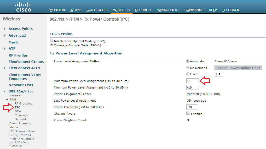
My customer is using a Cisco 3504 Wireless Controller running AireOS version 8.8. I am able to globally configure the Maximum Power Level Assignment to 15dBm.
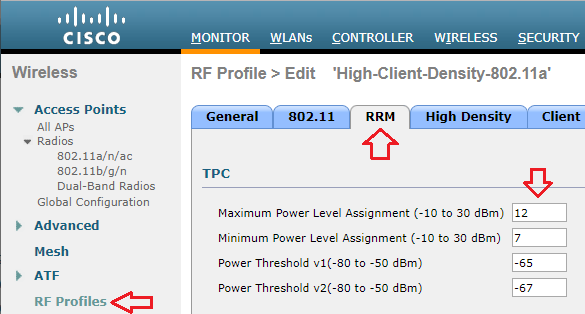
If the same controller were managing multiple locations with different requirements, I can also set a Maximum Power Level Assignment for different RF Profiles.
Though the maximum power level is configured in dBm, Cisco uses a series of numbers to represent levels of power. Phil Morgan of NC-Expert wrote an article titled WLC and AP Power settings in which he discusses Cisco power levels in further detail. In his article, he discusses how we can determine what the power levels represent as they vary by AP model, band (2.4 vs 5GHz), and even channel groupings (i.e. U-NII 1, 2, 2e, 3).
(Cisco Controller) >show ap config 802.11a ?

<Cisco AP>     Enter the name of the Cisco AP  or  <summary>.
summary        Displays radio summary of all APs

(Cisco Controller) >show ap config 802.11a AccessPoint2

[...]
    Tx Power
      Num Of Supported Power Levels ............. 6
      Tx Power Level 1 .......................... 17 dBm
      Tx Power Level 2 .......................... 14 dBm
      Tx Power Level 3 .......................... 11 dBm
      Tx Power Level 4 .......................... 8 dBm
      Tx Power Level 5 .......................... 5 dBm
      Tx Power Level 6 .......................... 2 dBm
      Tx Power Configuration .................... AUTOMATIC
      Current Tx Power Level .................... 2
      Tx Power Assigned By ...................... DTPC
[...]
I also stumbled upon an excellent post by Maxim Risman in the Cisco Community titled Cisco Access point 2802i Tx Power Chart where he demonstrates the use of another very helpful command which summarizes the power levels of all APs: show advanced 802.11a txpower
(Cisco Controller) >show advanced 802.11a txpower

Leader Automatic Transmit Power Assignment
  Transmit Power Assignment Mode................. AUTO
  Transmit Power Update Interval................. 600 seconds
  Transmit Power Threshold....................... -70 dBm
  Transmit Power Neighbor Count.................. 3 APs
  WLAN Aware TPC................................. Disabled
  Min Transmit Power............................. -10 dBm
  Max Transmit Power............................. 15 dBm
  Update Contribution
    Noise........................................ Enable
    Interference................................. Enable
    Load......................................... Disable
    Device Aware................................. Disable
  Transmit Power Assignment Leader............... Controller0 (192.168.1.100) (::)
  Last Run....................................... 10 seconds ago
  Last Run Time.................................. 0 seconds
  TPC Mode....................................... Version 1 Channel Aware NO


AP Name                          Channel            TxPower       Allowed Power Levels

--More-- or (q)uit
-------------------------------- ------------------ ------------- ------------------------
AccessPoint1                     (100,104,108,112)* *4/8 (13 dBm) [22/19/16/13/10/7/4/2]
AccessPoint2                     (64,60,52,56)*     *2/6 (14 dBm) [17/14/11/8/5/2/4/2]
AccessPoint3                     (36,40,44,48)*     *2/6 (14 dBm) [17/14/11/8/5/2/4/2]
AccessPoint4                     (100,104,108,112)* *4/8 (13 dBm) [22/19/16/13/10/7/4/2]
AccessPoint5                     (64,60,52,56)*     *2/6 (14 dBm) [17/14/11/8/5/2/4/2]
AccessPoint6                     (116,120,124,128)* *4/8 (13 dBm) [22/19/16/13/10/7/4/2]
Note that the range for the power levels actually does not change, but rather TPC is limiting the highest level that can be used.
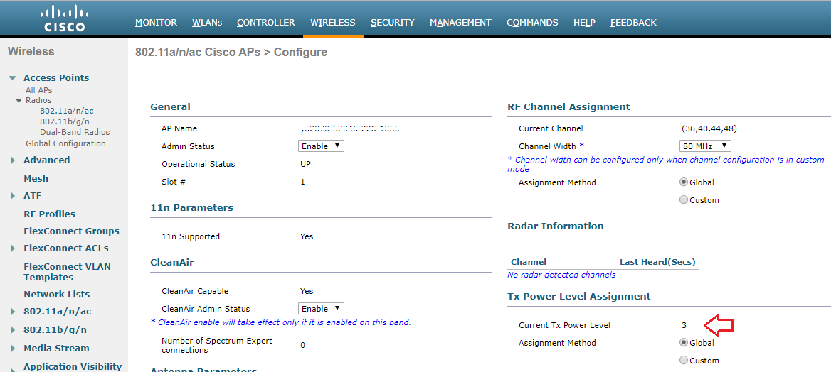
The current power level setting can also be found in the web GUI by navigating to Wireless > Access Points > Radios. There, you can see the power level for all of your APs in a column, or you can dive in to the configuration of a radio.
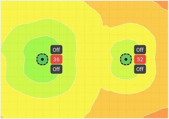
When performing predictive site surveys with Ekahau Pro site survey software, we have the ability to adjust the transmit power with which to generate our expected heat maps.
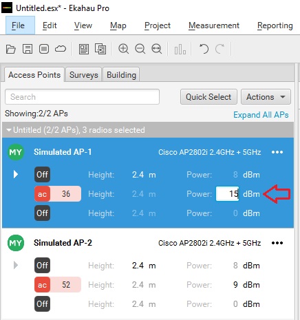
We can get an idea of how this difference may affect our design in the real world.
If you are interested in getting deeper into Cisco’s TPC implementation, you may want to check out a whitepaper they have published titled Transmit Power Control (TPC) Algorithm.